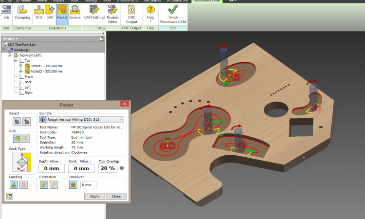
CAD+CAM vs Integrated system transfer of geometry
Today, furniture manufacturers often use a combination of two software tools for furniture design and CNC preparation.
- CAD+CAM: products from different manufacturers are used. For example, AutoCAD and MasterCAD or Autodesk Inventor and Alphacam, etc.
- Integrated systems: an integrated solution from the same manufacturer which include both CAD and CAM. For example, IMOS, Cabinet Vision, TopSolid’Wood, etc.
In this article I will not be making an in-depth comparison of the above solutions, instead I will be focusing on one distinct feature of these systems, namely the transfer of information from CAD to CAM.
As a rule, integrated systems ensure seamless transfer of information from CAD to CAM. These products come from a single manufacturer which makes sure the two systems are adjusted to each other, meaning that the geometry of the part automatically, without any additional processing, is transferred to CAM which automatically generates a required CNC program for part processing.
When CAD and CAM come from different sources, the transfer of information is not as smooth as with integrated systems.
It is perhaps fair to claim that DXF file is the most common method for transferring part geometry from CAD to CAM. Any reputable CAD system is able to generate a DXF format file and every CAM system is able to accept it.
When transferring information to DXF file, usually 2D (flat) drawing is used. While it is a proven method, furniture made from panels has several properties due to which additional information needs to be added when transferring geometry from CAD to CAM.
- The first property is edge banded parts. To make sure the part is properly processed, its contour in the DXF file must be displayed without the edge band. To achieve this, you have to additionally prepare a part model or modify the DXF file itself, or adjust oversize for part processing in the CAM itself.
- The second property is side cuts. A 2D part projection (usually, as seen from above) in the DXF file does not have options required to transfer information about side cuts, thus a designer (or a technologist) need to make a separate decision as to how the information about side cuts is to be transferred from CAD to CAM. Will they be additionally described/represented in the DFX file, or will this information need to be separately entered in the CAM environment – in any case, additional human input will be required.
Such additional input of information does not allow for seamless and automated transfer of geometry among systems and requires additional time resources from the designer or technologist, and could potentially lead to mistakes.
However, it is not the only aspect that distinguishes CAD+CAM from integrated systems. While integrated systems are superior in this regard, there are also other properties and some of them do not necessarily put integrated systems in a superior position to the CAD+CAM combination.


